

 English
 русский
 عربى
عربى

Новости отрасли
What is a wire edm?
2026-07-20
Контент
- 1 What Is a Wire EDM and How Does Wire Discharge Machining Work
- 2 The Wire Discharge Machining Process Step by Step
- 3 Materials for Wire EDM Machining: What Can and Cannot Be Cut
- 4 Core Wire EDM Components and Machine Structure
- 5 Types of Wire EDM Machines: Medium Speed, High Speed, and Large Taper Systems
- 6 Comparing Cutting Efficiency Across Machine Categories
- 7 General Adoption Trend of Wire Discharge Machining
- 8 Typical Material Distribution Across Wire EDM Applications
- 9 Radar Comparison of Machine Category Characteristics
- 10 Common Applications of Wire EDM Machining Across Industries
- 11 How to Select the Right Wire EDM Machine for Your Application
- 12 Manufacturing Background: Taizhou Xinchengyang Machinery
- 13 Maintaining Wire EDM Components for Consistent Cutting Results
- 14 Frequently Asked Questions About Wire Discharge Machining
What Is a Wire EDM and How Does Wire Discharge Machining Work
A wire EDM, short for wire electrical discharge machining, is a manufacturing process that shapes electrically conductive materials by generating a rapid sequence of controlled electrical sparks between a thin, continuously moving metal wire and the workpiece. This process is also commonly known as wire discharge machining or wire cut EDM, and it removes material through localized thermal erosion rather than mechanical cutting force. Because no physical cutting pressure is applied to the part, wire discharge machining is widely relied on for shaping hardened tool steel, carbide, and other tough conductive alloys that are difficult to machine with conventional milling or grinding tools.
During operation, the wire electrode is fed continuously from a supply spool, passes through upper and lower wire guides that keep it precisely positioned, and travels through the workpiece without ever making direct contact with it. A small working gap, generally in the range of 0.01 mm to 0.05 mm, is maintained between the wire and the material. Each electrical discharge vaporizes a very small volume of metal, and a dielectric fluid continuously flushes the eroded particles away from the cutting zone while helping to cool the wire and stabilize the discharge process.
Because material removal happens through electrical and thermal action instead of mechanical shear, wire EDM machining is well suited to producing components with sharp internal corners, narrow slots, and intricate profiles that would otherwise require several secondary operations.
The Wire Discharge Machining Process Step by Step
Although programming details vary by part geometry and machine model, most wire discharge machining jobs follow a similar sequence from setup through final part separation. Understanding this sequence helps operators plan fixturing, wire consumption, and cycle time more accurately before a job begins.
- Wire threading and tensioning: the electrode wire is loaded from the supply spool through the guide system and take up mechanism, with tension set to match wire diameter and material thickness.
- Workpiece setup and datum alignment: the part is fixtured on the worktable and aligned to a reference edge or datum hole.
- Path programming: the cutting profile is generated from CAD data or entered at the control, defining the contour and any taper requirements.
- Rough cutting pass: the first pass removes the bulk of the material along the programmed path at a comparatively higher discharge energy.
- Trim and finish passes: additional passes at reduced energy refine dimensional accuracy and surface finish.
- Flushing and swarf removal: dielectric fluid continues to circulate throughout the cut to clear eroded particles.
- Part separation: once the profile is complete, the finished piece is released from the surrounding stock.
Materials for Wire EDM Machining: What Can and Cannot Be Cut
The defining requirement for materials for wire EDM machining is electrical conductivity rather than hardness. Because the process erodes material through spark discharge, hardened tool steel, cemented carbide, and heat resistant superalloys can all be processed with wire discharge machining at a similar relative difficulty to softer conductive metals, while non conductive materials such as most ceramics, plastics, and glass generally cannot be processed unless a conductive surface coating is applied first.
| Material | Conductivity | Typical Application |
|---|---|---|
| Tool and die steel | Conductive | Stamping dies, punches |
| Cemented carbide | Conductive | Wear parts, forming tools |
| Titanium alloys | Conductive | Aerospace, medical parts |
| Nickel based superalloys | Conductive | Turbine components |
| Copper and brass | Conductive | Electrodes, connectors |
| Technical ceramics | Non conductive | Generally not processable |
Material thickness also plays a practical role in cycle planning. Thin sheet stock under 10 mm typically cuts quickly with minimal trim passes, while thicker blocks in the 100 mm to 300 mm range are common in die and mold work but require longer cycle times.
Core Wire EDM Components and Machine Structure
Understanding the main wire EDM components makes it easier to diagnose cutting issues, plan maintenance, and compare machine specifications. The diagram below outlines a general layout shared by many wire discharge machining systems.
The diagram above shows the general position of the wire spool, upper and lower wire guides, worktable, dielectric tank, and control panel relative to each other on a typical wire cutting machine. The wire path runs from the spool through the upper guide, down through the workpiece, and into the lower guide before reaching the take up system. This layout is broadly consistent across medium speed, high speed, and large taper machine categories, though exact positioning varies by manufacturer and model.
Wire supply, guides, and take up system
The wire spool feeds electrode wire through an upper guide, down through the workpiece, and into a lower guide before reaching the take up and collection system. Guide wear directly affects straightness and repeatability, which is why guide inspection is a routine maintenance task.
Power supply and pulse generator
The pulse generator controls discharge frequency, voltage, and current, shaping the energy of each spark. Lower energy settings generally produce finer surface finish at reduced cutting speed, while higher energy settings favor faster rough cutting.
Dielectric fluid system
The dielectric tank, filtration unit, and deionization resin maintain fluid conductivity within a working range, flush eroded particles from the cut, and help cool the wire and workpiece during discharge.
Types of Wire EDM Machines: Medium Speed, High Speed, and Large Taper Systems
Wire discharge machining equipment is generally grouped by wire travel method and cutting capability. Each category suits a different balance of accuracy, surface finish, and cycle time.
Medium Speed Wire EDM
Medium speed systems use a reciprocating molybdenum wire combined with multiple trim passes. This approach improves dimensional accuracy and surface finish compared with a single rough pass, making these machines a practical choice for mid volume die, mold, and tooling work where finish quality matters.
High Speed Wire EDM
High speed systems also use reciprocating molybdenum wire but are generally set up for efficient rough cutting throughput. These machines are widely used across general tool and die shops for profile cutting, blanking die production, and everyday prototype work.
Large Taper Wire EDM
Large taper systems are equipped with a U-V axis mechanism that tilts the wire guides to cut angled profiles. This capability is commonly applied to stamping die clearance angles, extrusion die production, and other tooling that requires a draft angle along the cut wall.
Comparing Cutting Efficiency Across Machine Categories
The horizontal bar chart below compares a relative cutting efficiency index among medium speed, high speed, and large taper wire EDM machines. High speed machines are positioned highest because their configuration is generally optimized for rough cutting throughput. Medium speed machines sit in the middle range since part of their cycle time is used on trim passes that improve finish quality. Large taper machines show a somewhat lower index because the tilting wire guide mechanism adds mechanical complexity that can influence cutting speed. These values represent a general relative comparison rather than fixed output figures for any specific job.
General Adoption Trend of Wire Discharge Machining
The line chart below presents an illustrative, indexed trend reflecting the general direction of wire discharge machining adoption within precision tooling manufacturing over recent years. The overall pattern trends upward, consistent with a broader manufacturing shift toward tighter tolerance requirements in die, mold, and precision component work. Growth in sectors such as electric vehicle tooling and aerospace component production has generally supported continued interest in wire EDM as a shaping method for hardened materials. This index scale is intended to show directional movement rather than an exact statistic and should be treated as general background context.
Typical Material Distribution Across Wire EDM Applications
The column chart below illustrates a general, representative distribution of material categories commonly processed with wire discharge machining across tool and die manufacturing. Tool and die steel typically represents the largest share, reflecting its widespread use in stamping and forming tooling, while cemented carbide follows as a smaller but consistent share tied to wear resistant tooling components. Aluminum, titanium and superalloys, and copper and brass make up the remaining categories, each linked to specific application areas such as prototyping, aerospace parts, and electrode production. This distribution is illustrative and will vary between individual shops depending on their customer base and product focus.
Radar Comparison of Machine Category Characteristics
The radar chart below compares medium speed, high speed, and large taper wire EDM machines across four characteristics: cutting efficiency, surface finish, taper capability, and precision consistency. Medium speed machines show a balanced shape with strength in surface finish and precision consistency due to multiple trim passes. High speed machines extend furthest along cutting efficiency but pull back on taper capability, reflecting their focus on throughput. Large taper machines clearly extend furthest along the taper capability axis, which reflects their dedicated U-V axis design for angled profile cutting. Reading across the three overlapping shapes helps illustrate that no single category leads in every characteristic, so machine selection depends on which characteristic matters most for a given part.
In the chart, the green shape represents medium speed machines, the blue shape represents high speed machines, and the muted navy shape represents large taper machines. Overlaying these three shapes makes it straightforward to compare trade offs at a glance rather than reading separate numeric tables for each characteristic.
Common Applications of Wire EDM Machining Across Industries
Because wire discharge machining works on any conductive material regardless of hardness, it appears across a wide range of manufacturing sectors, from everyday tooling shops to precision component suppliers.
- Stamping die manufacturing: punch and die profiles, clearance angles, and wear inserts
- Injection mold components: core and cavity inserts, ejector pin details, cooling channel features
- Aerospace components: turbine blade fixtures, titanium brackets, and superalloy parts
- Medical device parts: surgical instrument components and small precision fixtures
- Precision gears and templates: gauge blocks, gear profiles, and inspection templates
- Electrode production: graphite and copper electrodes used in sinker EDM operations
How to Select the Right Wire EDM Machine for Your Application
Choosing among medium speed, high speed, and large taper wire EDM machines generally comes down to matching machine capability with part requirements. The checklist below covers the factors that typically matter most during machine selection.
- Material thickness range: confirm the worktable clearance and wire feed system can handle both thin sheet work and thicker die blocks.
- Required surface finish: parts needing a finer finish generally benefit from multiple trim passes, which favors medium speed configurations.
- Taper cutting needs: any part requiring draft angles or beveled walls points toward a large taper U-V axis machine.
- Production volume: higher volume shops may prioritize cutting throughput, while lower volume precision work may prioritize finish quality per pass.
- Workpiece size and table travel: confirm X-Y travel and worktable load capacity match the largest parts expected in production.
Manufacturing Background: Taizhou Xinchengyang Machinery
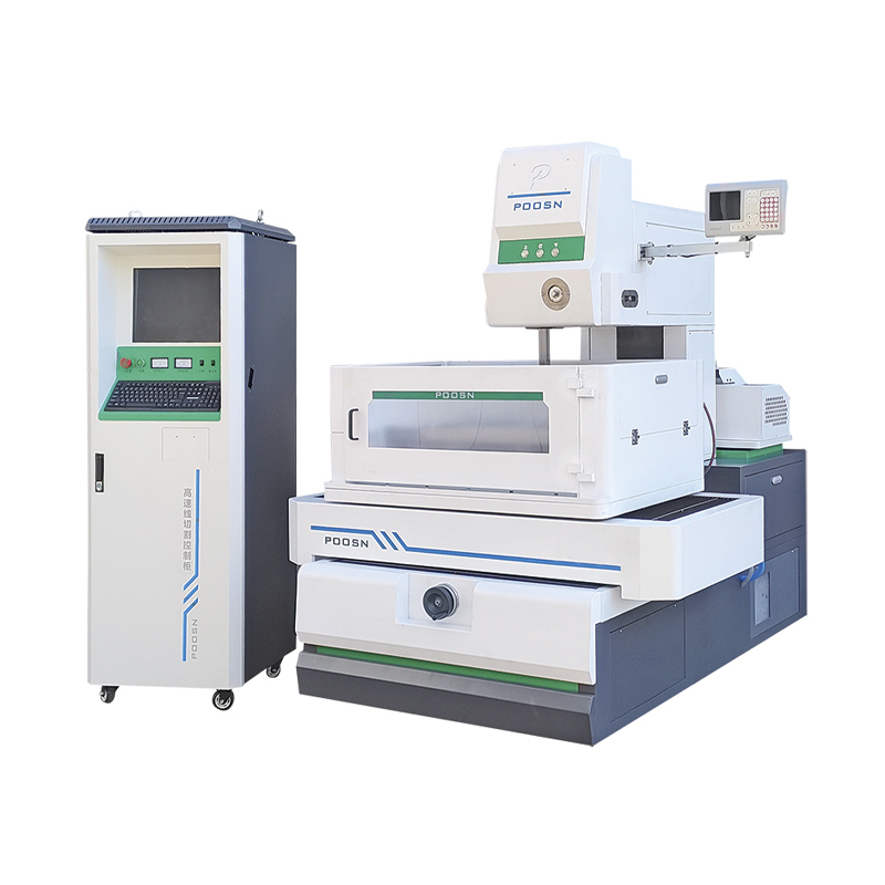
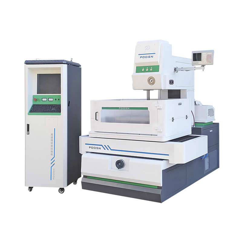
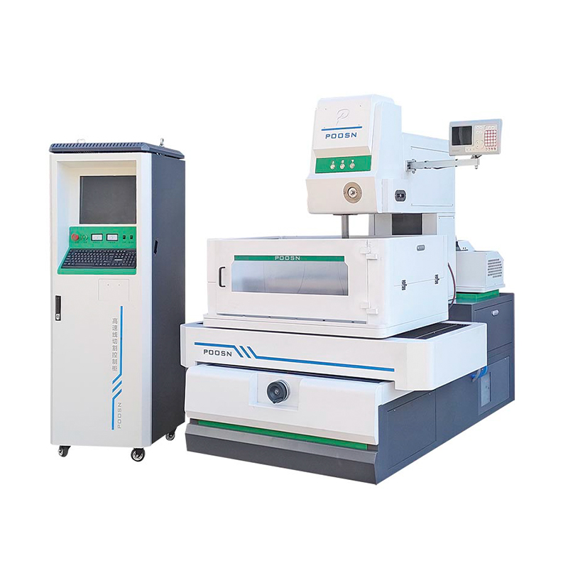
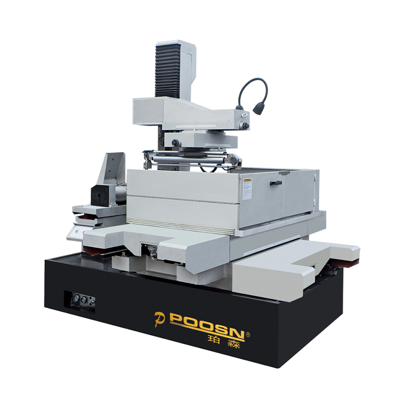
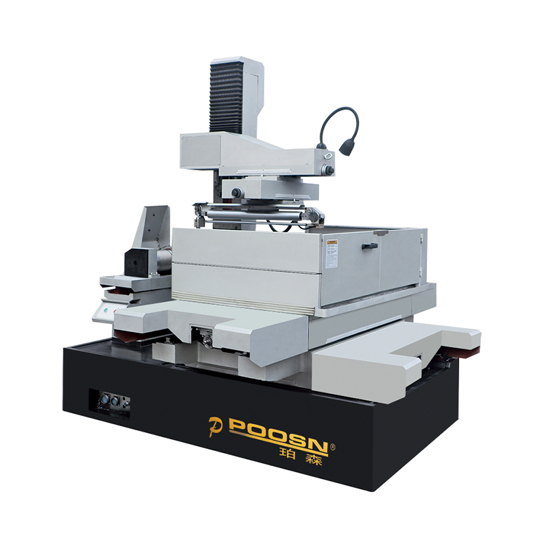
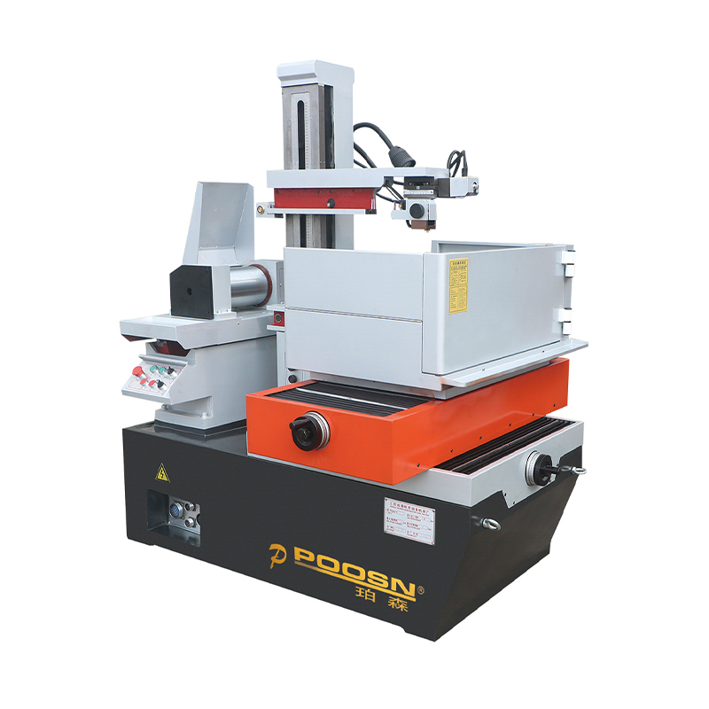
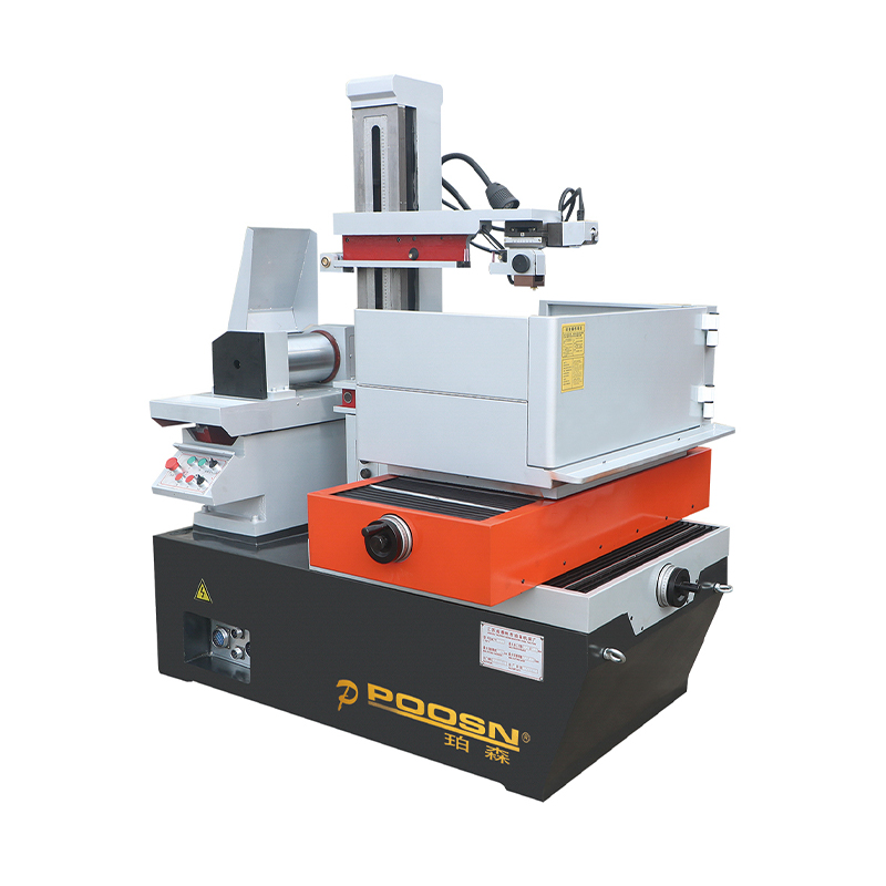
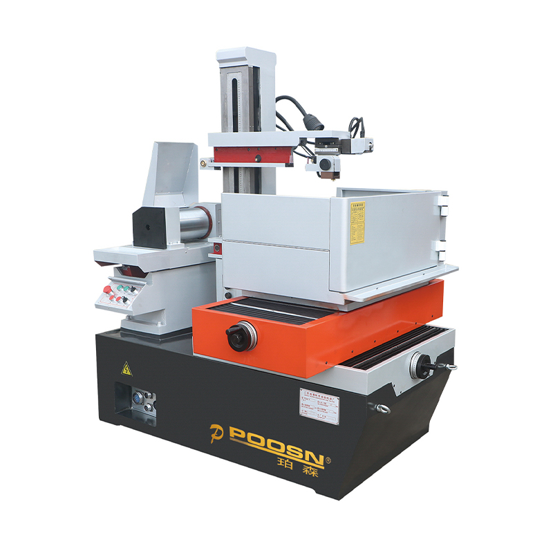
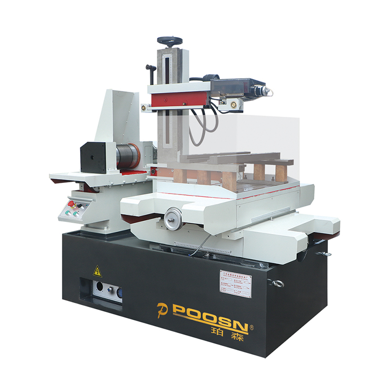
Taizhou Xinchengyang Machinery Manufacturing Co., Ltd is a manufacturer focused on the research, development, and production of electrical discharge machining equipment and related special processing technologies. The company product range covers the PS-C and DK77-BC medium speed wire cutting series, the DK77-A and DK77-B high speed wire cutting series, and the DK77-D large taper wire cutting series, giving customers a choice of machine categories aligned with the different cutting needs described throughout this article.
Each machine produced by the company goes through positioning accuracy testing as part of standard production practice, and the equipment is manufactured with reference to national manufacturing standards. Products are sold across domestic markets, with select models exported to Southeast Asia, West Asia, Europe, and the Americas. The company operates with a market oriented approach centered on quality and customer needs, supporting tooling and die manufacturers with practical, serviceable wire EDM equipment across medium speed, high speed, and large taper cutting categories.
Maintaining Wire EDM Components for Consistent Cutting Results
Routine maintenance keeps wire discharge machining results consistent over time and reduces unplanned downtime. The items below summarize maintenance areas that generally have the greatest impact on cutting accuracy and surface finish.
- Wire tension and guide wear: inconsistent tension or worn guides can introduce wire vibration, which shows up as wavy cut walls.
- Dielectric fluid condition: fluid resistivity and filtration directly affect discharge stability and cutting consistency.
- Flushing nozzle condition: worn or blocked nozzles reduce swarf clearance efficiency, particularly on thicker workpieces.
- Positioning accuracy checks: periodic verification helps confirm that a machine continues to hold its rated cutting tolerance over extended use.
Frequently Asked Questions About Wire Discharge Machining
What is a wire EDM used for
A wire EDM is used to cut precise profiles in electrically conductive materials, including hardened tool steel, carbide, and various alloys, for applications such as stamping dies, mold components, and precision tooling.
What materials for wire EDM machining are suitable
Any electrically conductive material can generally be processed, including tool steel, carbide, titanium, nickel based superalloys, aluminum, copper, brass, and graphite. Non conductive materials such as most ceramics and plastics are typically not suitable unless coated with a conductive layer.
What is the difference between high speed and medium speed wire EDM
Both use reciprocating molybdenum wire, but medium speed machines typically apply multiple trim passes to improve accuracy and surface finish, while high speed machines are generally set up for faster rough cutting throughput.
Can wire discharge machining cut thick materials
Yes, wire EDM machining can process thick blocks, with die and mold work commonly ranging from tens of millimeters up to several hundred millimeters, though cycle time increases with thickness due to flushing demands.
Which wire EDM components need the most frequent attention
Wire guides, flushing nozzles, and dielectric fluid filtration generally require the most frequent attention, since wear or contamination in these areas has the most direct effect on cutting stability and surface finish.
-
Телефон
+86-0523-86268788 +86-13815960366 +86-13912191163Эл. почта
[email protected]Адрес
Китай, г. Тайчжоу, р-н Хайлин, пос. Цзюлун, ул. Юйшэн, д. 366
